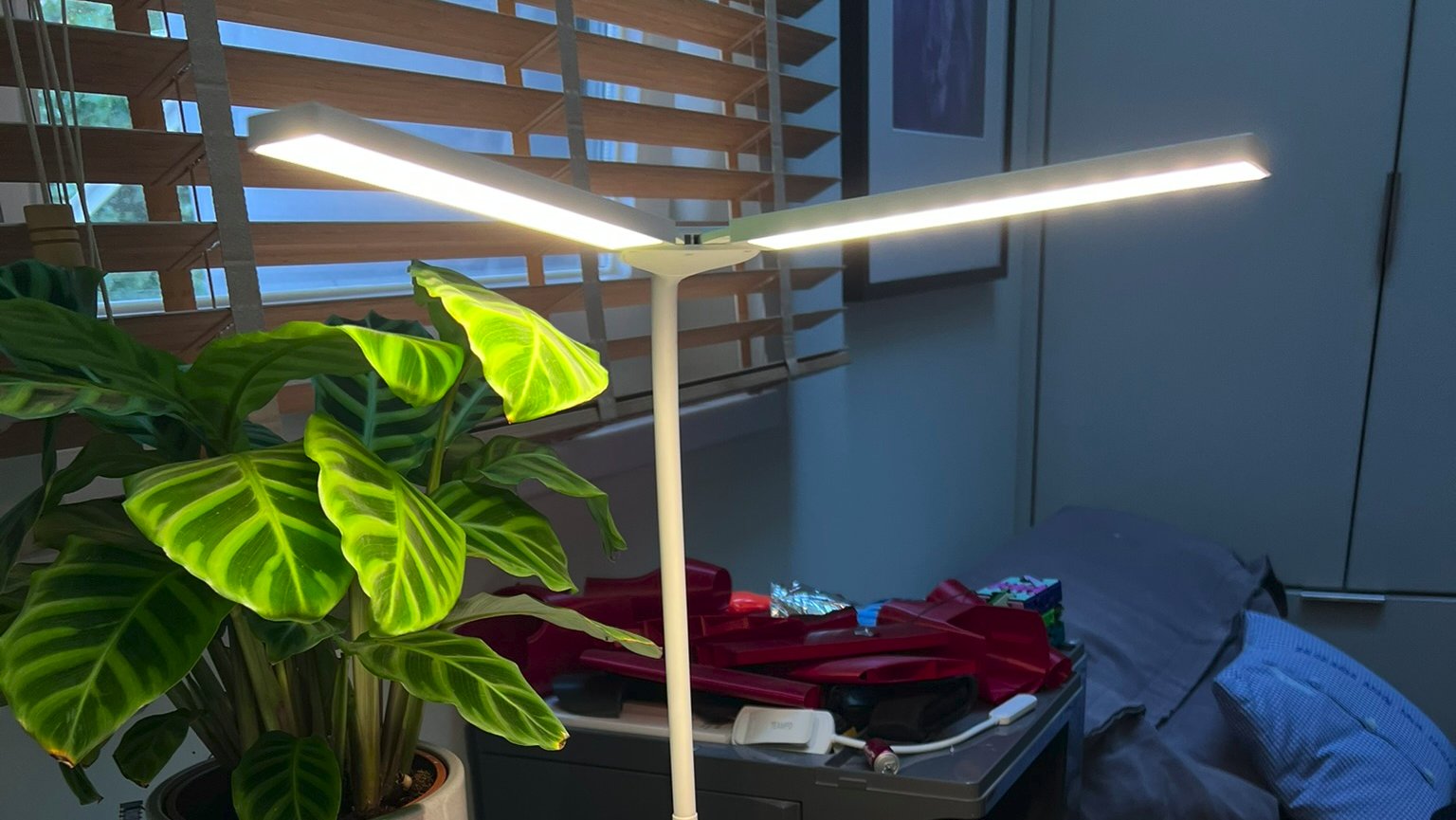
Making my desk lamp smart
I got gifted Desk Lamp a few years ago, it looks pretty good, and does its job of illuminating my desk. There is only one thing that always annoyed me, and kept me from using it all that much. It only has touch buttons on the thing itself, and I always have to reach over my whole desk if I want to turn it on.
I've tried using the easy solution of just putting it into a smart wall socket, but this thing doesn't remember its state. I can turn it off via the phone, but if I turn the socket on again, it doesn't turn on. Besides, I wouldn't be able to control the brightness and color temperature of the lamp.
After procrastinating taking it apart for way too long I finally committed. Luckily it was pretty easy, there were just some screws on the bottom and after removing those, you could just use one of these plastic separator chips to remove the bottom.
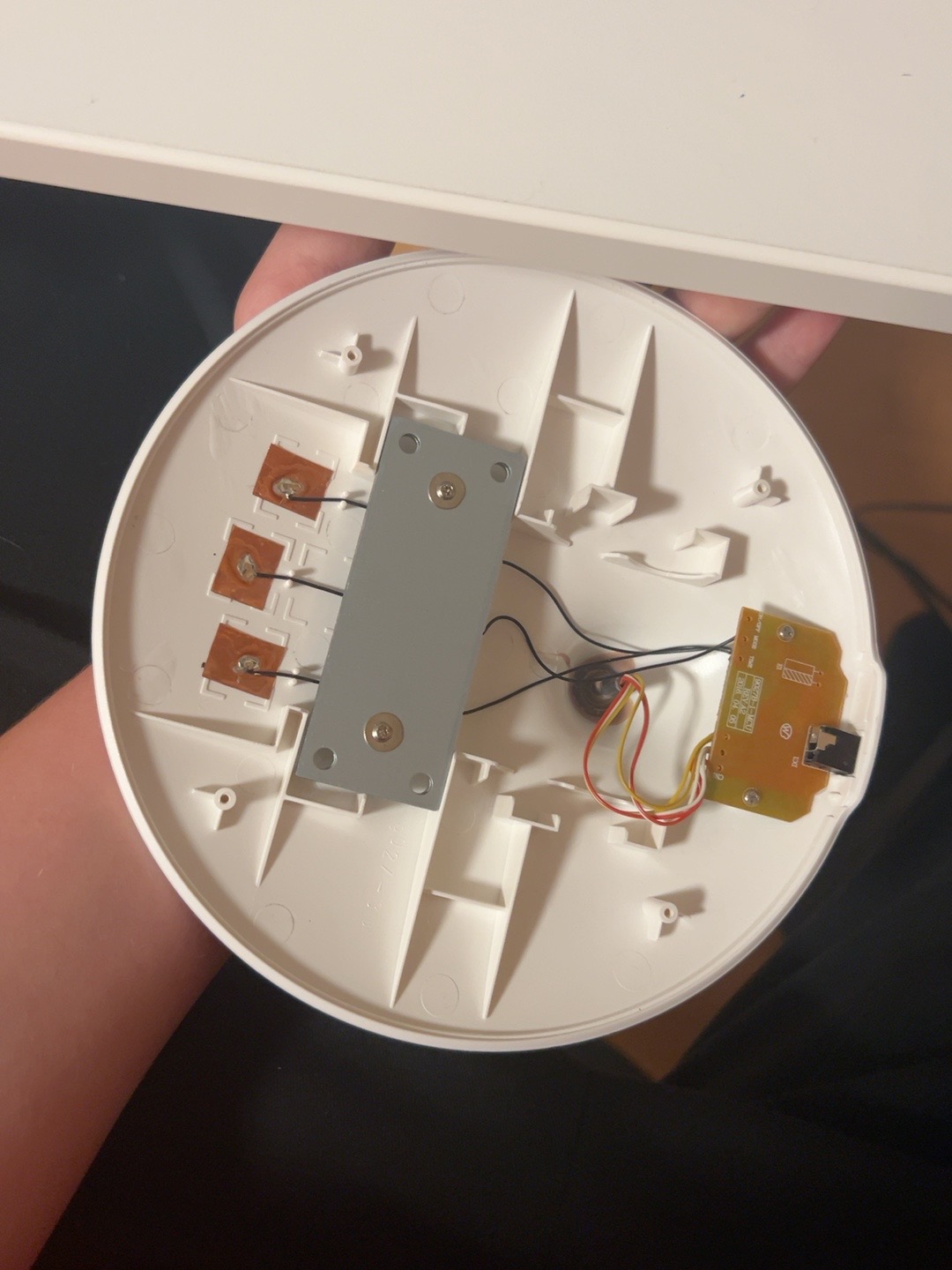
The electronics are pretty simple, it's basically just some capacitive touch pads (the copper things on the left), the circuit board for it on the right, and weight so it doesn't tip over. (Silver thing in the middle)
After removing the circuit board screws, and removing the board from the holder (which was way harder than expected) I saw this relatively simple board.
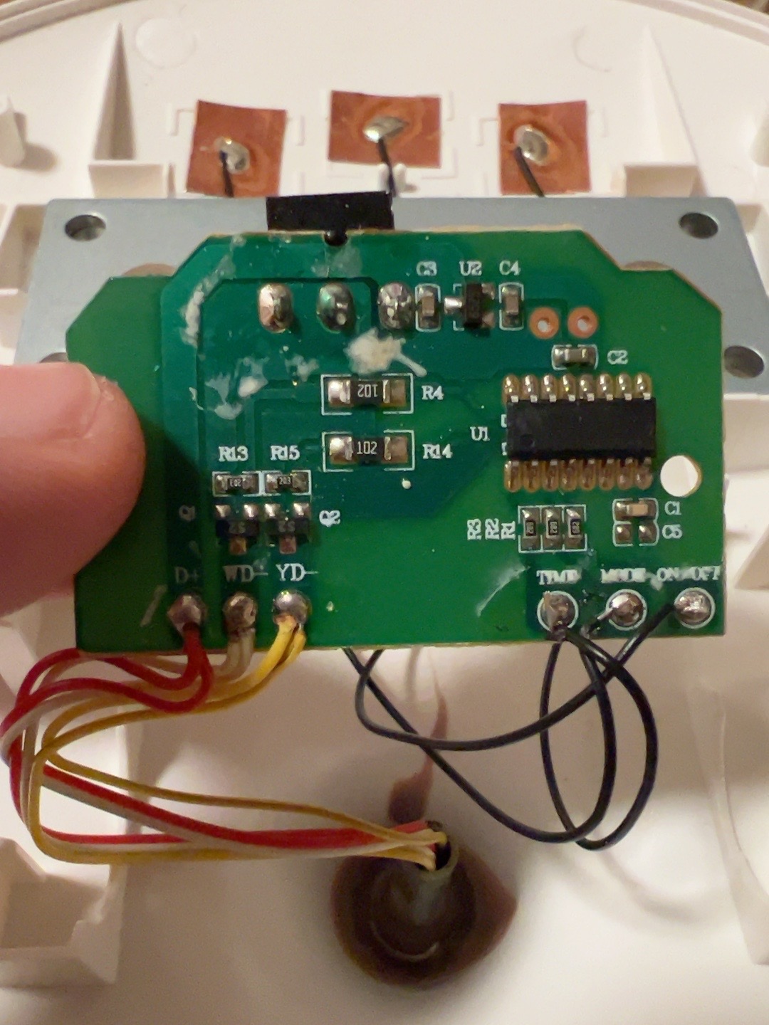
You can see the 3 black wires going to the touch pads for sleep timer control, color temperature control, and on/off.
On the left there are wires going to the LEDs. If you are wondering why there are always 2 wires soldered to one pad, it's because it's a lamp with 2 separate LED "wings". I don't see a reason why they put 2 wires here and didn't just split it at the top, but I don't really care. The separate yellow and white wires are used to control the warm-white LEDs and the cold ones separately.
I didn't want to disassemble the whole board and replace the old controller because it seemed much easier to just control the touch pads with my own microcontroller. Because they are capacitive touch pads, you can't just control them by closing a circuit like a normal switch, it just checks the capacity of the touch pad and if it changes, it knows it got pressed, and triggers the action.
Before I tell you about how that attempt failed miserably, I'm going to explain how I want it integrated into my smart home. I'm running Home Assistant, which is a self-hosted smart home controlling system. It has integrations for like ... everything. I bet I could connect my toothbrush to it.
WAIT THIS WAS MEANT AS A JOKE I COULD ACTUALLY CONNECT MY TOOTHBRUSH TO IT

Anyways, I want to use an ESP32 for this project (ESP32s are a series of low-cost microcontrollers made by Espressif, and they come in a lot of varieties). I'm using the ESP32-C3 SuperMini because it's cheap (mine cost under 2 euros) and, as the name suggests, very small.
Home Assistant has a neat integration for ESPHome devices. ESPHome lets you use these things without writing any code; you just have to write a simple configuration file. It also brings some other advantages, like changing the configuration of the device directly via Wi-Fi, which is very handy when said ESP sits inside a lamp.
Back to the failed attempt we go: By switching the GPIO from input to LOW, I tried to fake the same capacitance change a finger would cause. In theory that should work, but this touch sensor was way too sensitive. Even just connecting a loose wire already messed with it enough that it started detecting touches when nothing was actually pressing the button. After too much time messing with that, I finally gave up and tried actually controlling the LEDs myself.
I'm not good enough at soldering to remove the old chip and replace the individual pads with wires to my ESP, so I just wired around it. I disconnected the two negative LED wires from their pads on the lamp's circuit board and connected them to my MOSFETs (tiny electronic switches that can turn power to other components on and off) and Goddamn these things are small, it's impossible to get them to the right position, from like a meter you can't tell them apart from a small part of wire and I can confirm they are even worse to step on at night than Legos.
The only thing that saved me from insanity that night were these breakout boards I had lying around, it was a pain to solder the MOSFETs onto these boards, but after that I could use the relatively big soldering pads of the board.
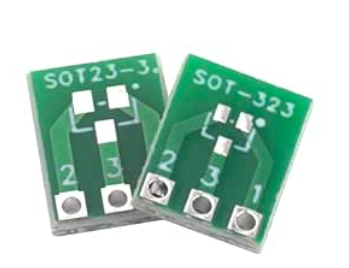
The rest was pretty simple, I connected the negative supply, the ESP32 control wires, and the wires for both LED wings to the MOSFET breakout boards, and after flashing the firmware I could control ... the warm white LEDs. Better than nothing, it proved that it could be controlled by my setup, but the cold white LEDs just refused to work. After changing the configuration a few times, and that not working, I figured I should just try another GPIO pin which surprisingly worked! My best guess would be that I broke it after soldering to it like 5 times while trying out different things, but I didn't really care to find the reason because it works flawlessly now, and I can fully control it with my Home Assistant, including brightness and color temperature.
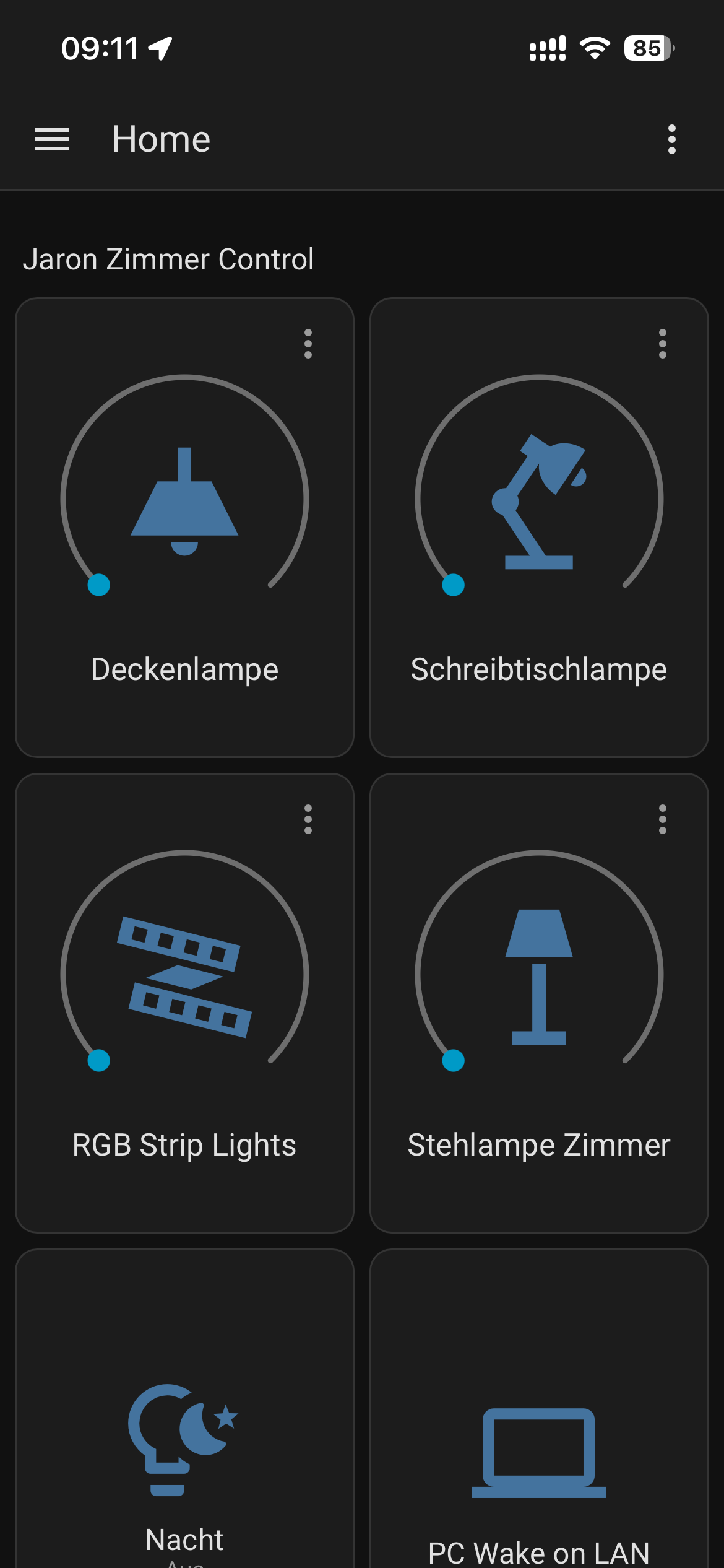
So, if you are broke like me, or just curious about it, I would definitely recommend you to check out how to integrate ESP32s into your home. Making my lamp smart cost me about 3 euros in parts.
Thanks for reading!
If you want to leave any feedback on this post, feel free to do so by just sending a mail to info@jkramertech.com